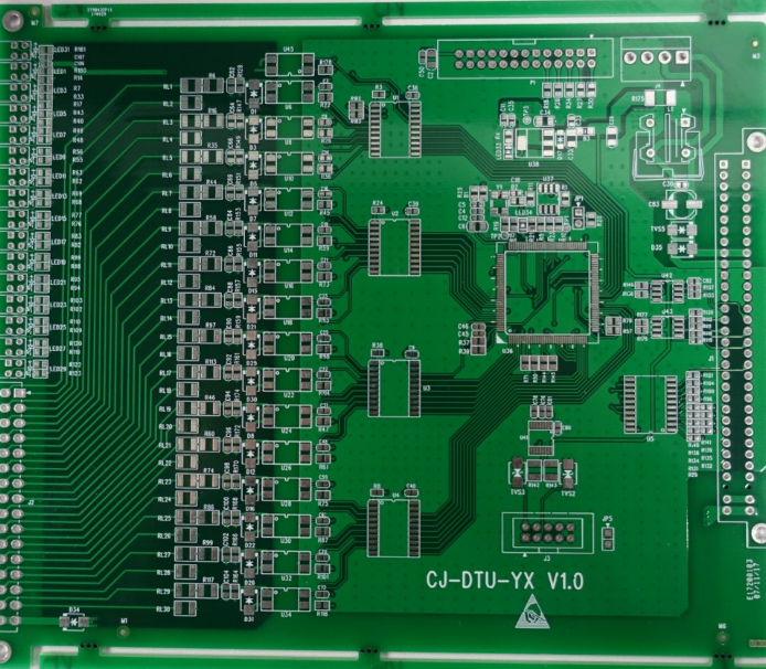

There are three possible ways to solve this: Vias placed close to SMD components may provide a path for solder wicking onto the back side of the board. Let’s look at each of these areas to see some instances where we might need to include or omit tented vias. Tenting can both aid and interfere with assembly, depending on the particular component being placed and soldered on the board.Tenting costs less than via plugging or filling/plating with an epoxy, making the simplest process you can use to protect vias.Tenting prevents exposure to environmental factors that reduce device lifetime, such as noxious chemicals or humidity.Some of the stated benefits and drawbacks of via tenting include: Tenting of vias is sometimes seen as a DFA requirement, as well as a reliability requirement. The solder resist reveal is the purple ring around the larger vias in this image. Example portion of a layout with tented and untented vias. If you look at a PCB layout, you can spot tented vias just by looking at your solder stop mask layer the same applies to the Gerber file for that solder mask layer.

The solder resist is placed to provide some measure of protection for the via pad and the plating inside the via barrel. The idea behind via tenting is simple: you’re covering any vias in your PCB with solder mask so that any pad/ring on the via hole, and the via barrel itself, are not exposed to the environment. In this article, we’ll examine some of these design points surrounding via tenting and when you should avoid using it in your PCB layout. Is this always the right practice? And what are the possible reliability concerns with tented vias? These are important questions, especially when reliability concerns get brought up in regard to high aspect ratio vias and stacked microvias. One of these is the use of tented vias, which is sometimes implemented in a PCB layout by default. Others are implemented without thinking about the potential problems, but only because those problems arise in corner cases. Some of these practices are misunderstood or implemented without best practices, such as copper pour in signal layers. There are some guidelines I see many designers implement as a standard practice, often without thinking about it.


 0 kommentar(er)
